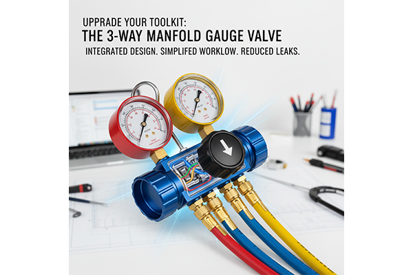
Upgrade Your Toolkit: What's the Efficiency Secret of the 3-Way Manifold Gauge Valve?
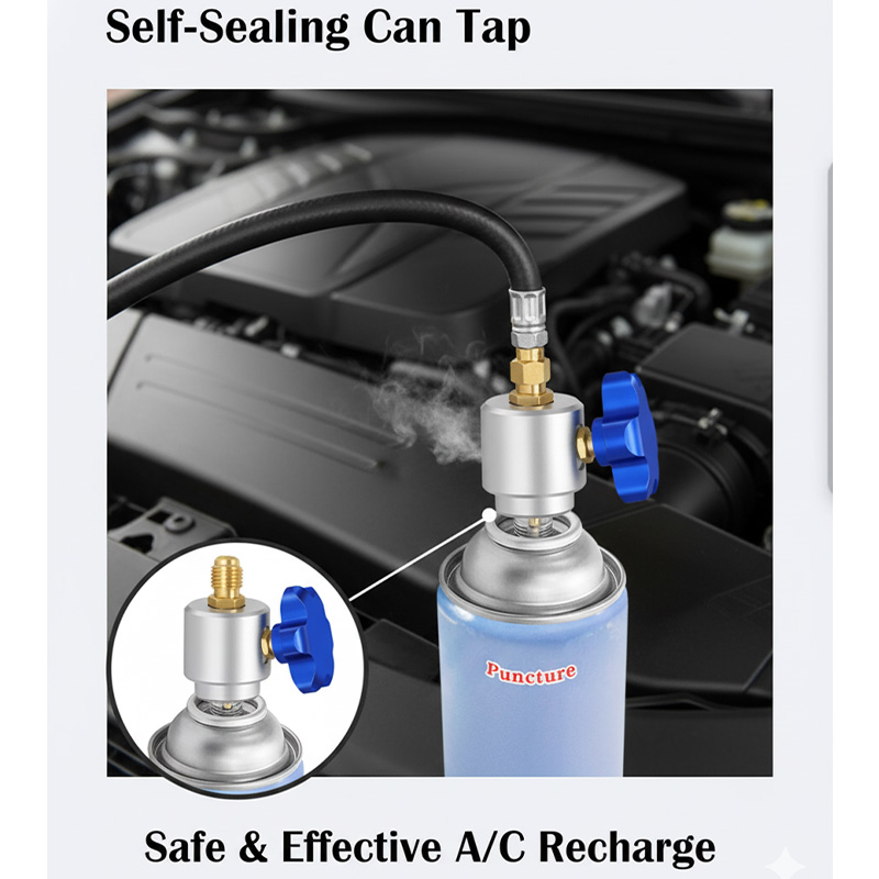
Frustrated by juggling multiple fittings and valves for a simple task? This traditional method is slow, messy, and increases the potential for costly refrigerant leaks at every connection point.
The secret is its integrated design. A 3-way manifold valve uses a single control knob to precisely manage the flow between three separate ports. This consolidation of control simplifies the workflow, reduces leak points, and makes AC service tasks significantly faster and cleaner.
I've always been fascinated by elegant solutions to complex problems. In mold design, we sometimes face issues where cooling, ejection, and filling all compete for the same small space. The best solution is often a single, cleverly designed component that serves multiple functions. The 3-way manifold valve is the perfect example of this philosophy in the tool world. For a designer like you, Jacky, the genius isn't just in the final tool, but in the intricate internal geometry of the valve that makes it all possible. It’s a masterclass in fluid dynamics and mechanical simplicity.
How does one valve control three different flow paths?
Confused about how a single knob can direct refrigerant without a chaotic mix-up? This uncertainty makes it hard to trust the tool for precise jobs like charging or evacuation.
The valve operates with a central rotating core that contains specific, isolated channels. As you turn the knob, this core aligns different channels with the three external ports, creating a clear, dedicated path for the refrigerant while sealing off the unused port.
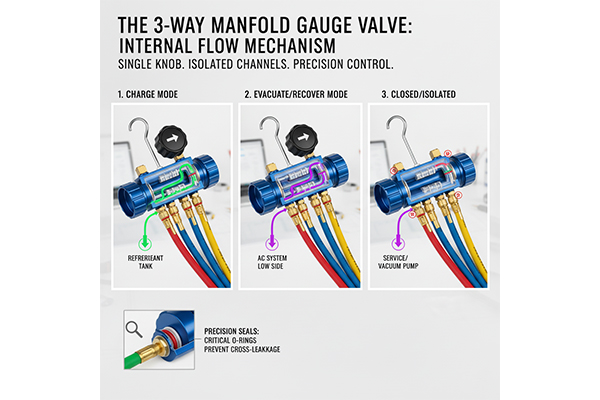
Think of it like a train switching yard controlled by a single lever. The valve's core is the track switch, and the refrigerant is the train. In the "charge" position, the core connects the refrigerant tank port to the system port. In the "recover" or "vacuum" position, it connects the system port to the service port. When closed, all ports are sealed off from each other. The real design challenge, Jacky, is in the tolerances and the seals. The O-rings that separate these channels must be perfectly placed to prevent any cross-leakage. The slightest imperfection in the machined valve body or the core could lead to a leak. It’s a precision instrument where a few thousandths of an inch make all the difference, just like in high-tolerance mold making.
Valve Position and Flow Control
| Valve Knob Position | Port A (Input) to Port B (System) | Port B (System) to Port C (Service) | Resulting Function |
|---|---|---|---|
| Open (Charging) | Connected | Sealed | Charges AC system from tank. |
| Open (Service) | Sealed | Connected | Connects system to vacuum pump. |
| Closed | Sealed | Sealed | Isolates all ports. |
What material choices are critical for a leak-proof valve?
Worried that a cheap valve will fail under pressure? Material failure can lead to stripped threads, refrigerant leaks, and a dangerous situation on the job.
A leak-proof valve demands professional-grade materials. The body should be forged brass for maximum strength, the internal moving parts made of durable metals, and the seals must be made from chemical-resistant elastomers like HNBR to withstand modern refrigerants.
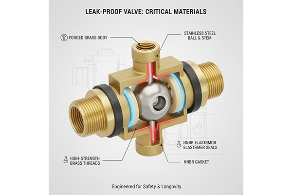
Material selection is everything; it's the foundation of a good design. In my CNC trading days, I saw firsthand how a component made from cast metal could fail unpredictably due to internal voids, while a forged part would withstand incredible stress. A professional valve body is forged, not cast, to eliminate porosity and create a dense grain structure that won't crack under hundreds of PSI. The seals are just as important. Standard NBR (Nitrile) seals will swell and degrade when exposed to the POE oils used with newer refrigerants. That's why high-end valves use HNBR (Hydrogenated Nitrile), which offers superior chemical and temperature resistance. As a designer, Jacky, you would specify these materials not just for performance, but for safety and longevity. It's the difference between a tool that lasts a season and one that lasts a career.
Component Material Breakdown
| Component | Economy-Grade Material | Professional-Grade Material | Design Advantage |
|---|---|---|---|
| Valve Body | Cast Aluminum/Zinc | Forged Brass | Resists cracking, corrosion, and thread damage. |
| Valve Core/Ball | Plastic or soft metal | Machined Brass or Steel | Smooth operation, long wear life, precise sealing. |
| Seals (O-Rings) | Neoprene or NBR | HNBR or Viton™ | High resistance to chemicals, oils, and temperature. |
| Control Knob/Handle | Basic Hard Plastic | Overmolded, ergonomic grip | Provides better control and comfort during operation. |
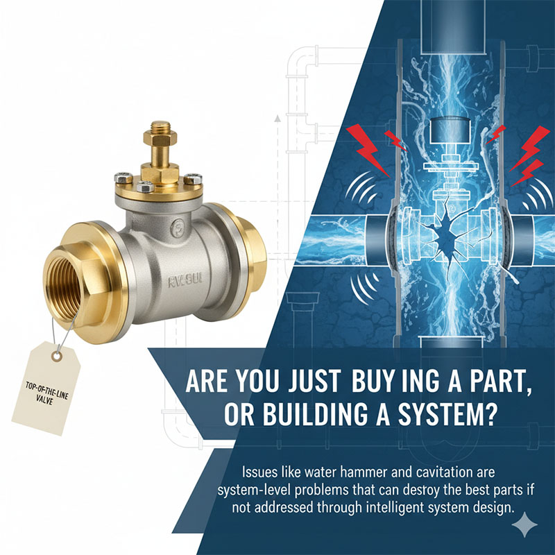
How does the valve design handle both high pressure and deep vacuum?
Wondering how the same seals can prevent leaks in both directions? A seal that holds back pressure might not be effective at stopping air from getting sucked in under vacuum.
The valve's effectiveness comes from its robust construction and bi-directional seals. Its solid metal body prevents flexing, while high-quality O-rings are designed to seal effectively whether the internal pressure is much higher or much lower than the outside atmosphere.
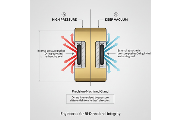
The physics behind this is quite interesting for a designer. Under high pressure, the refrigerant pushes the O-ring firmly into its groove, or "gland," creating a very tight seal. The real test is under a deep vacuum. The atmospheric pressure outside the valve (about 14.7 PSI at sea level) is now the force trying to get in. It pushes on the O-ring from the outside, seating it just as firmly in its groove but in the opposite direction. The key design element is the precision-machined groove that the O-ring sits in. It must be the perfect size and shape to allow the seal to function correctly under both of these conditions. If the groove is too loose, the O-ring can be pushed out of place. If it's too tight, the seal can be pinched and damaged. It’s a micrograms problem that requires micrograms solutions.
Sealing Forces at Play
| Condition | Dominant Force | Seal Action | Design Requirement |
|---|---|---|---|
| High Pressure | Internal system pressure pushes outward. | O-ring is compressed against the outer wall of its groove. | Strong valve body to contain force, precise gland. |
| Deep Vacuum | External atmospheric pressure pushes inward. | O-ring is compressed against the inner wall of its groove. | Perfect seal integrity to prevent air ingress. |
Conclusion
The 3-way manifold valve's secret is its brilliant, consolidated design. It enhances efficiency and safety by integrating multiple functions into one robust, precisely engineered component, upgrading any toolkit.